


 English
 Français
 عربى

Industry News


Meter Box Cable Entries: What Must Be Agreed Before Drilling?
2026-11-06
The meter box has arrived, but the cable route approaches from a different direction than expected. An installer can see a convenient flat surface and may be tempted to make a new opening. For a project purchaser, that is the point at which a small layout omission becomes a documentation and installation problem.
Cable entries belong in the enclosure discussion before the purchase order is released. Their location affects cable bending, gland selection, internal equipment clearance and service access. A box with enough external space may still be awkward to wire when these details are left to site improvisation.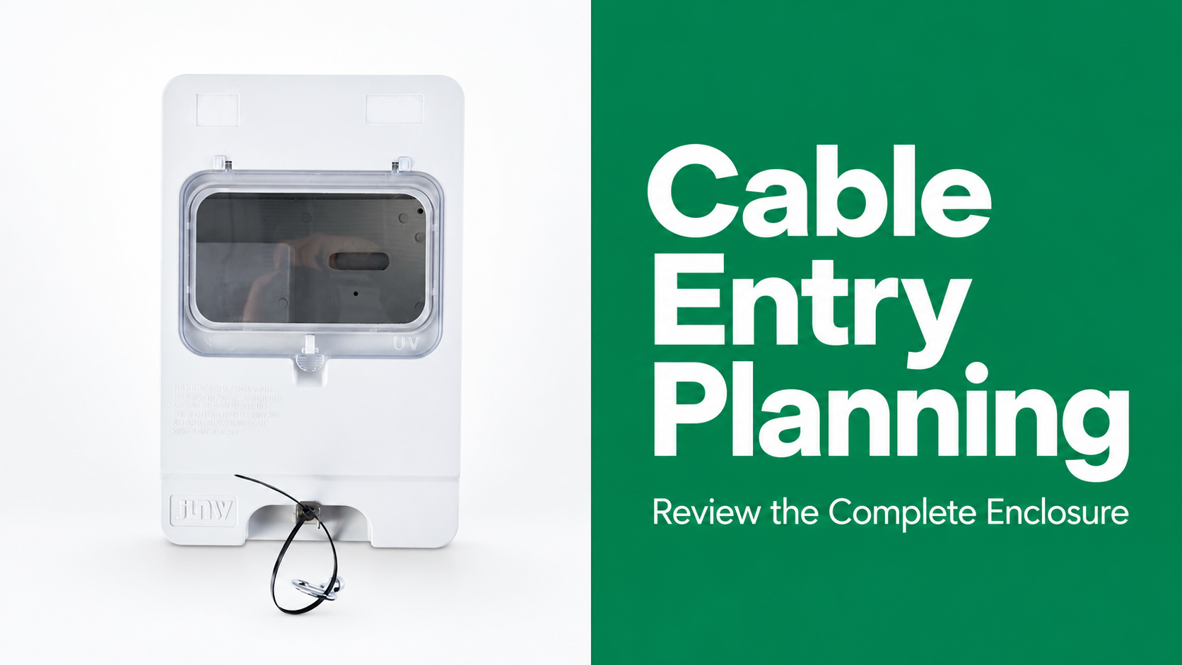
Draw the entry route before choosing a hole
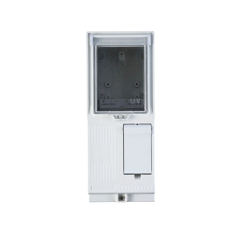
The CIU meter box provides a product reference for this discussion; confirm the exact ordered version and its supporting documents before applying the checklist.
Begin with the direction from which each cable reaches the enclosure. Show the incoming and outgoing routes separately. The drawing should identify whether cables enter from below, behind or another approved location, together with any nearby wall, conduit or mounting surface that limits access.
Distinguish factory-prepared openings, knockouts and plain surfaces. A photograph alone may not establish which areas can be modified. Ask for the current enclosure drawing and installation instructions, and resolve any proposed drilling or cutting with the enclosure supplier and responsible electrical designer.
Match the interface as a complete arrangement
A cable entry is more than a hole diameter. It may require a gland, sealing washer, locknut, conduit fitting or blanking component. Each part must match the cable and enclosure arrangement. Do not infer that an accessory is included because it appears in an illustration of a possible installation.
Cable outside diameter is relevant to a gland's sealing range, while the mounting thread and panel opening describe another interface. Confusing these dimensions can produce an accessory that fits the enclosure but does not suit the actual cable. Keep both sets of dimensions on the entry schedule.
| Planning item | Information to record | Why the distinction matters |
|---|---|---|
| Cable | Type and actual outside diameter | Determines the cable interface |
| Entry opening | Location and prepared geometry | Determines enclosure fit |
| Accessory | Thread, fixing and sealing arrangement | Establishes the complete connection |
| Unused entry | Approved closure method | Prevents an unfinished opening |
| Internal route | Bend and equipment clearance | Keeps wiring practicable |
The table is a planning aid, not an approval of a particular gland or field modification. Final selection must follow the equipment documents and project requirements, including any applicable installation rules assessed by the qualified project team.
Check the space inside the closed enclosure
Place the cable route on the internal layout. Consider where the cable leaves its gland, where it bends and where it terminates. A route that looks clear with the door open may interfere with a latch, cover, viewing window assembly or internal device once the box is closed.
Allow for the installation sequence as well. If a locknut cannot be reached after the meter or mounting plate is fitted, the drawing should make the required order of work clear. Service access also deserves attention: a cable connection that can only be inspected after unrelated equipment is removed may create avoidable maintenance work.
- Show each entry with a unique identifier on the drawing.
- Keep gland and cable dimensions in separate columns.
- Confirm access for fixing and tightening the selected accessories.
- Check the closed-door envelope and internal covers.
- Identify who supplies every gland and closure component.
- Refer unresolved modifications to the responsible designer.
Avoid adding a universal bending allowance to every project. Cable construction and manufacturer instructions affect the required bend radius. Ask the cable or system designer to establish the applicable requirement, then check that requirement against the actual enclosure arrangement.
Keep enclosure ratings tied to the documented configuration
An enclosure rating should be read with its conditions and the supplied configuration. Making a new opening or changing an entry accessory can alter the completed arrangement. The purchasing file should not imply that every possible combination automatically inherits a catalogue statement about the unmodified box.
Ask which entry details were included in the documented product configuration and what instructions apply to installation. If the project requires a particular level of protection, the responsible parties need to establish how the complete installed assembly meets that requirement. A supplier's general product description is not a substitute for the relevant evidence.
This is especially important when several contractors contribute parts. The enclosure supplier may provide the box, an electrical distributor may supply glands, and a site team may route the cables. A shared entry schedule prevents each party from assuming another has checked the interface.
Turn the discussion into a receiving check
Before shipment, approve the drawing revision that shows the agreed entry arrangement. On receipt, compare hole locations, accessory quantities and blanking parts with that revision. Record any differences before the enclosure is altered or installed; otherwise it becomes harder to establish whether a discrepancy was supplied or introduced later.
Keep the entry schedule alongside the equipment layout and installation instructions. When a cable specification changes, review the entry rather than updating only the termination list. The most useful order is one that arrives with the interfaces already understood, so the installer can follow a planned arrangement instead of inventing it beside the wall.
Keep a separate note of any site conditions that were not represented in the approved sample. This helps the project team decide which questions are resolved by the supplied enclosure documents and which still require an installation review before work begins.
CONTACT
 Unit 2, Building 18, Phase II, Dongtou Emergency Industrial Park, Wenzhou, Zhejiang Province, China
 +86-13587789751
 junwei@jvele.com
KEEP IN TOUCH
Copyright © Zhejiang Junwei Electric Co., Ltd. All Rights Reserved
Record number:浙ICP备09058387号
Junwei Electric Component Manufacturer
